A Minimalist Approach to Doorbell Circuit Diagrams Wireless Doorbell. The use of old and traditional doorbells which generally run a wire to your AC mains is slowly becoming obsolete due to a number of reasons. Firstly, the wiring itself is a running electrical and fire hazard. In case the wiring terminals and the doorbell casing start taking on moisture, for example in rainy weather.

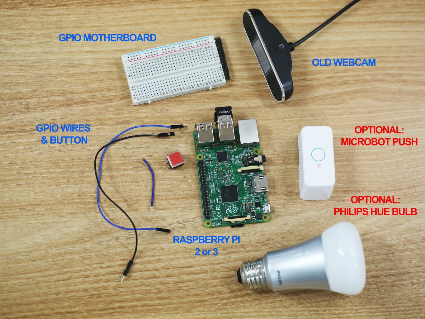
A wireless doorbell circuit diagram can help you install a doorbell without having to worry about putting a gaping hole in your wall, running wires around your house, or hiring an electrician. Installing a wireless doorbell circuit diagram isn't as difficult as it looks. With just a few basic tools and supplies, you can have a wireless doorbell In this instructables, we will make an Arduino based Wireless Doorbell using simple hardware. This project is uses an RF Module for wireless communication and also an Arduino UNO board to analyze the data. Design of Transmitter Circuit The transmitter consists of a 434 MHz RF Transmitter Module, HT - 12E Encoder IC, 750 KΩ Resistor and a

How To Make A Wireless Doorbell Circuit Using A 433 MHz RF Transceiver Circuit Diagram
A simple wireless doorbell circuit is discussed in the following post which can be constructed at home. Written and Submitted By: Mantra. 303MHz TRANSMITTER with 32kHz Crystal. The initial circuit we are going to explore has a 32kHz crystal to crank out a tone which means that the receiver is unable to false-trigger.
Next to that I sometimes here of interference problems with other wireless doorbells so the more reason to make one of your own. When the doorbell switch is pressed this circuit sends a message via a simple 433 MHz RF transmitter to a wireless doorbell receiver while keeping the original doorbell functionality intact. The circuit is placed in

Making a Wireless Doorbell Circuit Circuit Diagram
Arduino RF Transmitter Circuit Diagram. Our wireless doorbell project will require a transmitter and receiver circuit each with its own Arduino board. The Circuit diagram for Doorbell Transmitter is shown below . The Arduino pin 5 is connected to the one end of the doorbell switch, and the other end of the switch is connected to the supply voltage. Wireless doorbell circuit diagrams are essential for understanding the various components and connections involved in creating a wireless doorbell system. These diagrams provide a visual representation of the circuitry and help users understand how the different parts work together to produce the desired functionality.